Page 10 of 17
AS11.5-6 | Advanced Airway Indications and Mechanical Ventilation Settings — SDL Guide (Part 2)
Principles of Mechanical Ventilation
Mechanical ventilation is the use of a machine (ventilator) to perform or assist the work of breathing. It achieves two physiological goals: oxygenation (ensuring adequate PaO₂ by delivering an appropriate FiO₂ and maintaining alveolar recruitment) and ventilation (CO₂ elimination by generating adequate minute ventilation). Understanding mechanical ventilation begins with understanding the distinction between these two goals, because they are controlled by different ventilator parameters.
The two fundamental modes of mechanical ventilation encountered by medical students are:
Volume-controlled ventilation (VCV): The ventilator delivers a set tidal volume (VT) with each breath. The respiratory rate (RR) is set, and together they determine the minute ventilation (VE = VT × RR). The airway pressure generated varies depending on the patient's lung compliance and airway resistance — the ventilator does not control pressure, it controls volume. VCV is the most common mode used in the operating theatre.
Pressure-controlled ventilation (PCV): The ventilator delivers each breath to a set pressure (driving pressure above PEEP). The tidal volume delivered varies with changes in compliance and resistance. PCV is often used in ICU patients with stiff lungs (ARDS) where pressure limitation is important to prevent ventilator-induced lung injury.
Pressure support ventilation (PSV): A partially assisted mode in which the patient triggers each breath and the ventilator provides a set level of pressure support to augment the breath. Used during weaning. In PSV, the patient sets the rate and the ventilator augments each breath.
The concept underlying all modes is the respiratory cycle: gas flows into the lungs when the ventilator creates a pressure gradient between the circuit and the alveoli (inspiration), and returns during exhalation when the airway pressure drops below alveolar pressure (passive recoil). The pressure needed to inflate the lungs depends on respiratory compliance (how stiff the lungs are) and airway resistance.
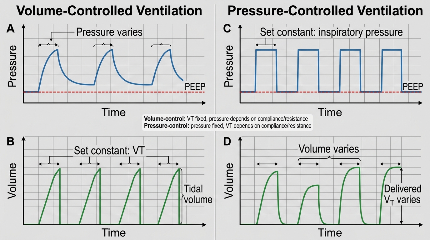
Volume-Controlled vs Pressure-Controlled Ventilation
Key Ventilator Settings: Tidal Volume, Rate, PEEP, and FiO₂
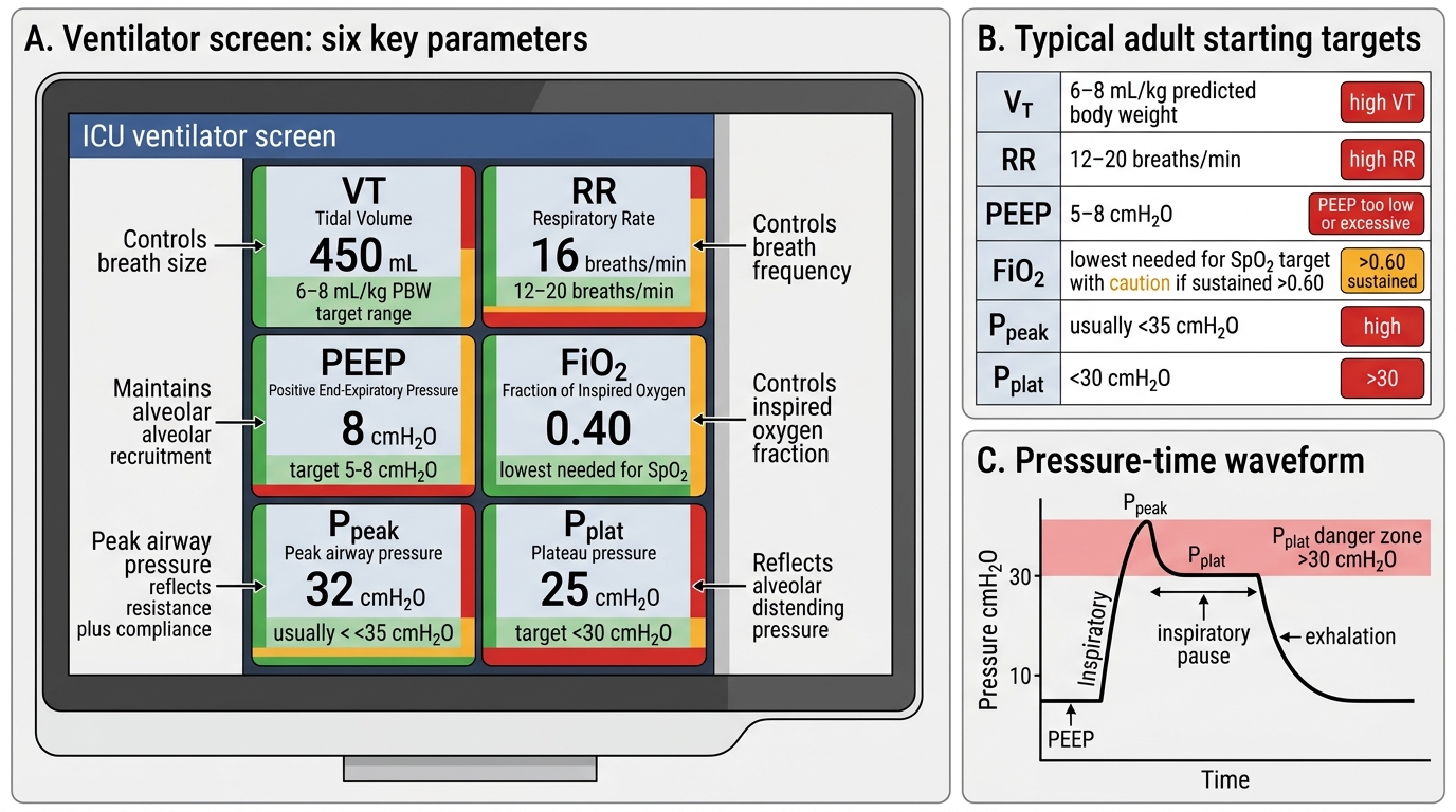
Competent understanding of mechanical ventilation requires knowing the purpose, typical value, and consequences of incorrect setting for each of the key ventilator parameters. These are the parameters you will read on a ventilator screen and will be expected to interpret in clinical assessments.
Tidal volume (VT): The volume delivered with each breath. In lung-protective ventilation (the current standard of care for all ventilated patients, not just ARDS), VT is set at 6–8 mL/kg of ideal body weight (IBW), not actual body weight. IBW for males ≈ 50 + 0.91 × (height in cm – 152.4) kg; for females ≈ 45.5 + 0.91 × (height in cm – 152.4) kg. Using actual body weight in an obese patient leads to over-sized tidal volumes, elevated plateau pressures, and ventilator-induced lung injury (VILI). The classic non-lung-protective tidal volume of 10–12 mL/kg IBW is now considered harmful in most patients.
Respiratory rate (RR): Set at 12–16 breaths/min for most adults. Increased rate increases CO₂ clearance (raises alveolar ventilation); decreased rate retains CO₂. In ARDS, higher rates (20–30/min) may be used with low VT to maintain minute ventilation. Auto-PEEP (air trapping from incomplete exhalation) is a risk at very high rates in obstructive lung disease.
PEEP (positive end-expiratory pressure): A baseline positive pressure maintained at end-expiration that keeps alveoli open (prevents collapse), recruits collapsed alveoli, and improves oxygenation. Physiological PEEP is 3–5 cmH₂O. In ARDS, PEEP is titrated upward (typically 8–15 cmH₂O or higher) to maintain SpO₂ ≥88–95% while minimising FiO₂. Excessive PEEP causes haemodynamic compromise by reducing venous return and right ventricular afterload.
FiO₂: Set as a fraction (0.21 to 1.0). Initial FiO₂ is often set at 1.0 (100%) at intubation to rapidly correct hypoxaemia, then titrated down to the minimum FiO₂ that maintains SpO₂ ≥94% (or 88–95% in ARDS). The target is to avoid both hypoxia and hyperoxia. FiO₂ >0.6 sustained for >24–48 hours risks pulmonary oxygen toxicity.
Plateau pressure (Pplat): Measured by applying an end-inspiratory pause (no flow); reflects alveolar distending pressure. Target ≤30 cmH₂O. Pplat >30 cmH₂O signals alveolar overdistension (barotrauma risk) — respond by reducing VT.
Driving pressure: Pplat minus PEEP; reflects the stress applied to the lung parenchyma per breath. Target <15 cmH₂O in ARDS.
Key Ventilator Parameters and Safety Ranges
Monitoring Ventilated Patients: ABG Interpretation and Alarm Response
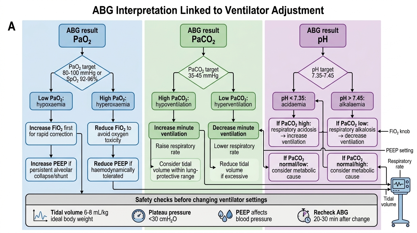
Monitoring the mechanically ventilated patient is a dynamic and continuous process that integrates both electronic surveillance of ventilator parameters and periodic arterial blood gas (ABG) analysis to assess the physiological adequacy of ventilation and oxygenation. Unlike spontaneously breathing patients, who self-regulate their ventilation in response to PaCO₂ and pH feedback, the ventilated patient is entirely dependent on the clinical team to interpret the data and make the appropriate adjustments. The ABG is the primary quantitative tool for this purpose: it is the only method that simultaneously measures PaO₂, PaCO₂, and pH, allowing a complete picture of respiratory and metabolic status. In practice, an ABG is obtained 20–30 minutes after any change in ventilator settings, at regular intervals (every 4–8 hours in ICU), and whenever the clinical situation changes (new hypotension, desaturation, agitation). Understanding how each ABG result maps to a specific ventilator parameter — and what change to make and by how much — is the practical skill this section develops.
The key ABG parameters and their ventilator correlates are:
• PaO₂ (normal 80–100 mmHg on room air; acceptable ≥60 mmHg on ventilator): controlled primarily by FiO₂ and PEEP. Low PaO₂ → increase FiO₂ or PEEP; high PaO₂ → reduce FiO₂ first (then PEEP) to avoid oxygen toxicity.
• PaCO₂ (normal 35–45 mmHg): controlled by alveolar ventilation = (VT – dead space) × RR. High PaCO₂ (hypercapnia) → increase minute ventilation (increase RR or VT within safe limits). Low PaCO₂ (hypocapnia) → decrease RR or VT.
• pH (normal 7.35–7.45): reflects the balance of PaCO₂ (respiratory component) and HCO₃⁻ (metabolic component). Respiratory acidosis (low pH, high PaCO₂) → increase ventilation. Permissive hypercapnia (pH 7.20–7.30, PaCO₂ up to 50–60 mmHg) is accepted in ARDS to avoid injurious tidal volumes.
• SpO₂: continuous non-invasive surrogate; target ≥94% (or 88–95% in ARDS).
Common ventilator alarms and responses:
• High peak pressure alarm: check for patient biting tube, kinking, secretion plug, bronchospasm, or pneumothorax
• Low minute ventilation alarm: check for circuit disconnection, cuff leak, apnoea (in assist-control mode)
• Desaturation: check FiO₂, PEEP, tube position (right mainstem intubation causes left lung collapse), sputum plugging
ABG-Guided Ventilator Adjustment